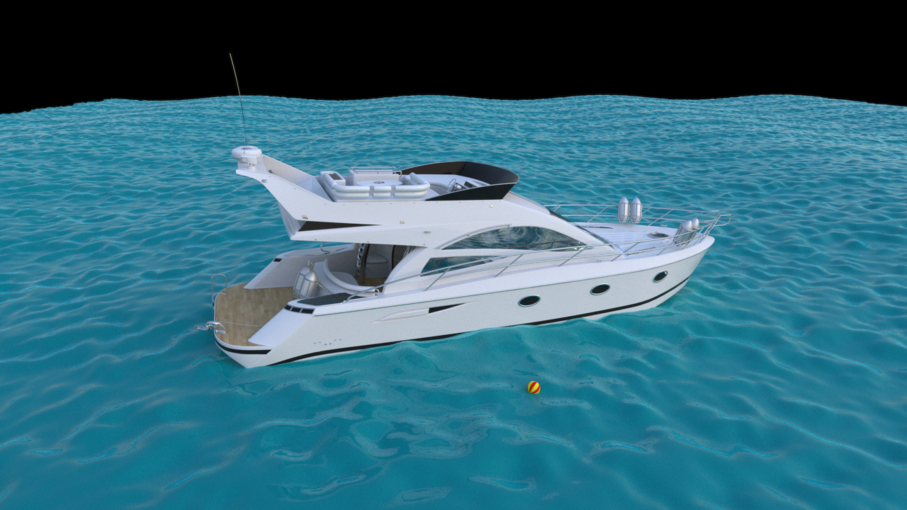
I’m on holiday on the South coast this week, and after amazing weather, this morning it’s had the audacity to rain, so I thought I’d see how difficult it would be to make a fake-but-sometimes-plausible procedural texture for emulating waves on the sea via displacement.
Jerry Tenssendorf’s paper “Simulating Ocean Water” is essentially the way to do it accurately, using a discrete Fourier Transform, which allows very accurate modelling of wave peaks and troughs based on the wind interaction and gravity, and indeed other waves around them.
I only had a couple of hours I wanted to devote to it, and couldn’t get into that level of detail, so I tried to fake it by just using Simplex noise modulated by the sine of the texture coordinates.
Basically, at a very simple level (ignoring wind which is pretty important for accurate simulation), the peaks and troughs of waves on the sea closely resemble a trochoid, which can be emulated with the sin() function. I ended up modulating two different resolutions of these waves (major primary waves and smaller secondary waves) on top of each other along with noise, which at least for non-open-water waves (open water waves crests tend to have angled peaks when it’s windy and when the number of waves increases) with moderate wind, gives reasonable results. It’s certainly better than just random noise. But it’s very rigid and consistent even with the noise modulation, so for large areas it basically looks like a tiled texture.
At some point, I’d like to investigate implementing Jerry Tenssendorf’s paper to do it accurately.
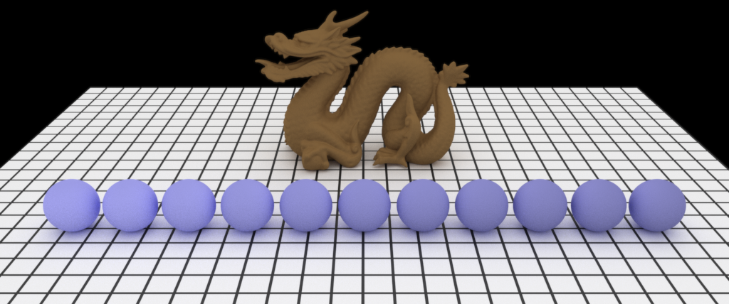
I’ve had this code kicking around for ages, but it never worked correctly, due to a bracket in the wrong place! Finally got it working, so Imagine can do realistic diffuse rough surfaces like clay.
The image below shows spheres with incremental roughness values, and a terracotta dragon.
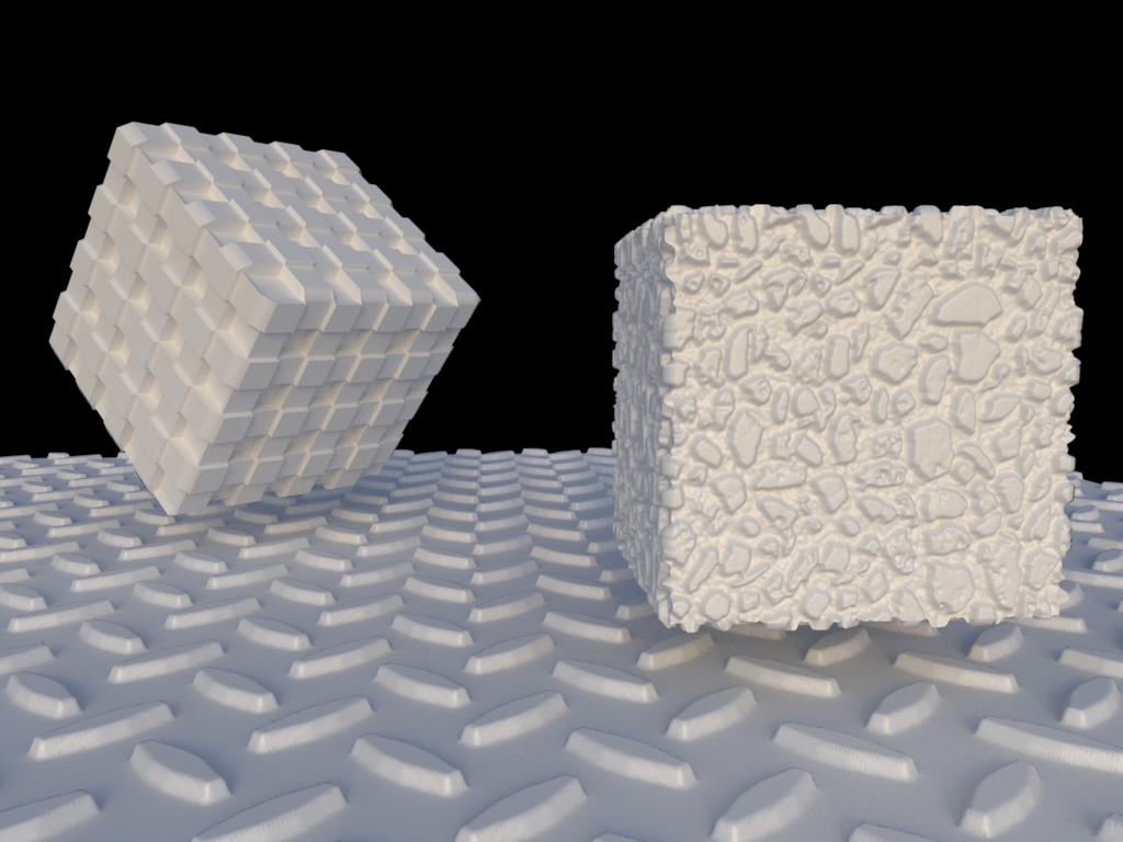
I’ve now added initial support for displacement of geometry after subdivision using displacement maps. It’s far from perfect yet - it’s quite slow when subdividing to the number of levels required for decent results (the two cubes above are 6.2m faces, subdivided 10 times), and the Half-Edge data structures I’m using for subdivision use a fair amount of memory, and there’s a very slight amount of faceting that doesn’t look normal.
The first two issues (speed and memory consumption) I can probably fix quite easily by making my Half Edge data structures more compact and efficient - currently, each Half Edge Vertex, Half Edge Edge and Half Edge Face store pointers to each other which while easy, consumes more memory than required. Converting them to using offset indexes (like my KDTree does) should bring memory usage down by half (instead of storing an 8-byte pointer, it’s possible to store a 4-byte uint_32 for an offset into a table).
It’s also not on-the-fly micro-polygon displacement - that’s more difficult (and slower while rending), can only be done on triangles (loop SubD is the normal variant) but uses much less memory and allows easy adaptive stopping criteria by checking each edge length in camera-space to see whether it’s smaller than a pixel yet.
There’s also vector displacement (displacement in three dimensions, as opposed to simply along the vertex’s normal), which should be pretty trivial to implement.
Imagine has had support for Catmull-Clark subdivision of quads within its interface for a while now, but the previous implementation had several limitations: it was slow and memory-inefficient (it just brute-forced the subdivision from the original faces), it didn’t support open shapes with holes and it didn’t keep UVs.
I’ve now re-written this to use a half-edge mesh structure, which makes it faster (less duplicate work is done), it supports boundary edges (holes in geometry), supports triangles and it subdivides UV positions (linearly at preset). I’ve also added support for linear subdivision with no smoothing.
Once I sort out the Geometry Instance infrastructure for each object in order to allow Geometry Modifiers at render time, it should be fairly simple to add Displacement support.
Discussion at work led to talking about implementing a wireframe shader in Nuke, so I decided to see how difficult
it would be in Imagine. As long as the mesh consists of polygons of a single type - i.e. triangles or
quads: not difficult at all it turns out.
For triangles, it’s easy enough to emulate a wireframe surface by simply working out how close a hit position
on a triangle is to an edge by transforming the triangle’s points into world space and then using the standard
point-to-line method of a perpendicular vector to each edge. This gives you the distance in world space of the
hit position to each edge, and based on which distance is the closest, you can then apply a step function to
the colour of the surface, based on the distance and a line thickness amount.
For quads, I first tried using the same algorithm as for triangles, but ignoring the edge of the triangle that was
shared within the quad. This worked to some degree, but each quad had two opposing wedges in the corners where the
point-to-line formula meant that parts of some edges weren’t shaded correctly.
So instead, I decided to use the Barycentric coordinates of the hit position within the triangle. This allowed me to correctly isolate all four edges of the quad based on a fixed threshold, but I then had to work out the line width and keep it uniform to the length of any edges. In the end I multiplied the Barycentric coordinates of both the the hit position and the inverse hit position (for the opposing edge of the quad) by the length of each of the non-shared edges of the triangle, giving a distance. The smallest of these distances I then used to step the colour, as I did for triangles. While this might not be perfectly accurate and work in all situations, it seems to work very well in practice and also allowed me to (almost) match the line thickness to the triangle method. It also looks very nice:
There’s a very slight (~1%) overhead in shading, as triangles have to be fetched and transformed to world space, but both of the renderings above at full HD finished in under six minutes with 676 samples per pixel.
When I sort out the texturing infrastructure to make it more flexible, it should be very easy to apply this texture as an alpha texture for a fully-3-dimensional mesh that is able to be seen through and cast shadows.
After recently trying to render an animation with Imagine, the result consisting of heavy aliasing in the form of walking and flickering edges on small objects, I realised that I couldn’t put off adding proper Reconstruction Filtering to Imagine any longer.
With no filtering, each sample which contributes to a pixel’s final colour has equal weighting to the final result, which leads to heavy aliasing as objects move across the frame. Using Reconstruction Filtering, the sample’s weighting to the final result is related to its distance from the centre of the pixel.
There are many different kinds of filters that can be used for Reconstruction Filtering, ranging from Box filtering (which is the same as no filtering - at least with a default filter width of 1), Gaussian (smooth, slightly blurred) to Lanczos Sinc (very sharp, having negative lobes). Unfortunately, no filter is perfect for every scenario, although generally for stills, you can get away with sharper filters.
I’ve implemented Triangle, Gaussian and Mitchell Netravali filters currently, which along with Box (no filtering) you can see enlarged examples of below: